
Dimming in the 21st Century
A guided tour of the contemporary dimming landscape
15 June 2015
Text:/ Andy Ciddor
While dimming may not be at the leading edge of the technologies used in our profession, it retains a critical place in our design toolkit. Indeed, dimming has become so simple to implement and so reliable that to many of us it has just become the black box in the corner that controls the level of our fixtures. Perhaps it’s time to open up the black box and have a peek inside a 21st century dimmer.
The first thing you may notice when you focus in on dimming is the wide variety of technologies available to go in your black box. These include phase control, reverse phase control, sine wave, direct optical dimming, pulse width modulation and constant current reduction. Most of these technologies are great for direct-driven incandescent sources, others work well with transformer-driven incandescents. One technology can dim externally-ballasted sources like linear fluorescents and even metal halide discharge lamps. A couple of these work well with LEDs, while optical dimmers can control everything, especially the light sources that can’t be dimmed electrically.
OPTICAL
The earliest known dimming technologies were variations on the same optical dimming tricks we use today to control the light from sources such as candles, the sun, and many families of discharge lamp. They involved using a range of ingenious shutter mechanisms or pieces of cloth to progressively obscure the light source. Today’s DMX-controlled, motorised louvres may have a more sophisticated control mechanism but they still work by blocking the light with an opaque material.
In the early days of electric lighting the majority of dimming was achieved with resistances and, after the introduction of alternating current, with auto-transformers (variacs). Although we’ve walked away from these crude mechanically-operated technologies and their incredibly-inefficient all-electric successor, the saturable reactor, these cumbersome monsters from the first half-century of electric lighting were generally much kinder to the supply network than most of today’s technologies.
ELECTRONIC
The overwhelming majority of contemporary electronic dimmers work by chopping chunks out of the power feeding the lamp. The older and more robust technologies take out big chunks just once in each half cycle of the mains power, while the newer and more agile devices take out delicate little nibbles, but do so much more often. Any device that chops up the power to a lamp this way produces distortions in the power supply, especially at the triplen (3rd, 9th, 15th, etc) harmonics of the power supply frequency. In addition to the problems caused for all other electronic devices connected to the distorted supply, these harmonics produce substantial currents in the supply neutral and in substation transformers. Any sizable dimmed installation must be designed with the harmonic distortion issues in mind, particularly where dimmers are being retrofitted to existing undimmed installations.

PHASE CONTROL
The very first all-electronic dimming technology, Phase Control has been around for about 80 years. In its earliest incarnation, using Thyratron valves as the switches, it was neither sufficiently reliable nor anywhere near affordable enough to make it popular. The technology finally came into its own in the 1950s with the appearance of an affordable and highly robust solid state switching device, the SCR (Silicon Controlled Rectifier). This was later supplemented by other solid state devices such as the Triac, the Metal Oxide Silicon Field Effect Transistor (MOSFET) and most recently, the Insulated Gate Bipolar Transistor (IGBT).
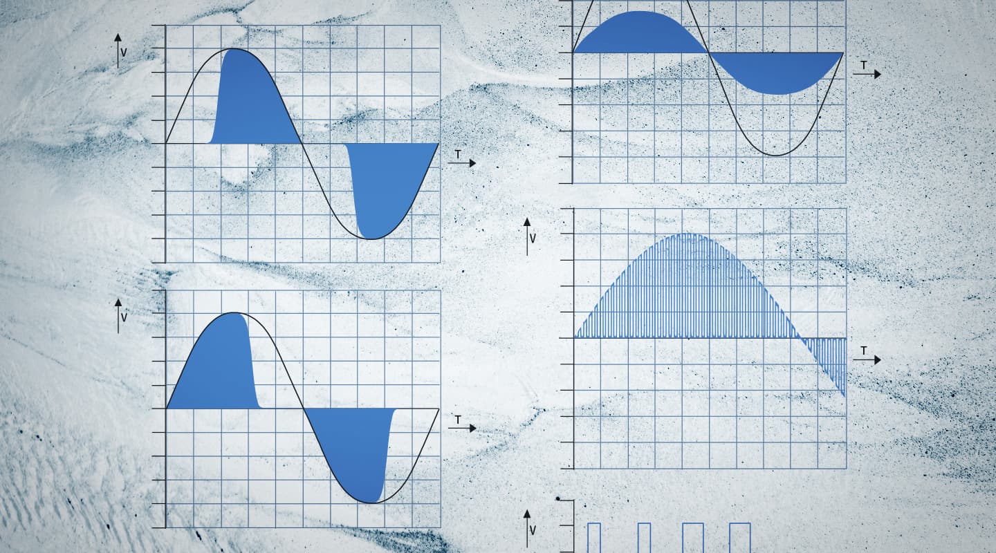
The basis of phase control dimming is quite simple. Rather than attempting to restrict the amplitude of the current flowing through an incandescent lamp, as earlier forms of dimming had done, it works by switching off parts of each cycle of the alternating current supply. You might expect the resulting chopped current to cause the dimmed lamp to flicker, but the thermal mass of the filament smooths out the current output and it just gets cooler and less bright as the missing chunks get larger.
The SCR is a solid state switching device that only conducts current in one direction (like a rectifier diode), although it doesn’t conduct at all until triggered on. However, once an SCR starts conducting, it snaps rapidly from fully-off to fully-on, producing very little waste heat, but it is extraordinarily difficult to turn off. This doesn’t really matter as the current stops flowing at the end of the half-cycle anyway. As an SCR can only handle current flowing in one direction, a pair of them is required to handle the alternating current supply. The Triac was a later development that is essentially an inverse pair of SCRs in a single device, although not quite as robust. As SCRs and Triacs are much easier to switch on than off, the unwanted part of the power cycle had to be cut from the start (or leading edge) of each cycle, hence the name Forward Phase Control.
Phase control is a long way from being the perfect dimming process. Switching on the current to a lamp partway through a cycle brings with it some serious side effects. The sudden surge of current in the lighting cables and luminaires produces a ferocious burst of electromagnetic interference (EMI) that finds its way into everything from unshielded audio and video cables to cousin Wilf’s hearing aid.
The inrush of current to the lamp being dimmed also brings with it mechanical stresses that not only shorten the working life of the filament but also cause it to vibrate at audible frequencies, a phenomenon known as a ‘singing’ (the filaments aren’t really singing – they’re humming, because they don’t know the words). To reduce these problems, a substantial choke inductor is incorporated into the load circuit to slow down the switch-on. As such an inductor is generally both large and heavy, this limits the possibilities for both portability and miniaturisation of low-interference dimmers. Despite these shortcomings, the majority of dimmers installed over the last half century are variations on the forward phase control concept.
Phase control is also the preferred technology for controlling low-voltage lamps being fed by inductive (iron cored or magnetic) transformers.
REVERSE PHASE CONTROL
Power MOSFETs and IGBTs are essentially very high powered transistors. Unlike Triacs and SCRs, they can not only be switched on and off with relative ease, they can also be switched on and off s-l-o-w-l-y, to reduce the production of harmonic distortion and EMI. These devices can be used to make dimmers that don’t require a substantial choke inductor or even dimmers that chop their chunks of power out from on the trailing edge of power cycle, a process known as Reverse Phase Control.
Switching the power slowly generates a lot more heat in the IGBT or MOSFET than is produced in SCRs or Triacs. These dimmers are characterised by their need for more aggressive thermal management and require larger heatsinks, thermal monitoring, and often also noisy fans. While it may be possible to make a more compact dimmer without a big inductor, the need for heat dissipation prevents the dimmers from shrinking very much in size.
There has been much discussion as to whether or not reverse phase control dimmers actually produce less EMI or mains distortion when dimming lamps but there is no doubt that they are much better for dimming low-voltage incandescent lamps that are fed through ‘electronic transformers’. These ‘electronic transformers’ are actually switch-mode power supplies which are much happier drinking their current from the front end of the power cycle. Some MOSFET and IGBT based dimmer systems can dynamically switch between forward and reverse phase control.


SINE WAVE
Like the switch-mode power supply units used in most modern electronics, sine wave dimmers use pulse width modulation (PWM) of a switching device (in this case an IGBT) to control their output. Each cycle of power is divided up into a fixed number of slots (usually between 400 and 600 of them) and the amount of time that the IGBT is switched on during each slot (the width of the power pulse) is used to vary the amount of power being allowed through the dimmer.
This strategy ensures that there is no sudden inrush of current and no substantial distortion of the power waveform, producing an output power cycle that looks remarkably like the sine wave shape of the original power supply, only lower in amplitude. However, to achieve this feat, these dimmers incorporate very sophisticated monitoring and control electronics and complex cooling systems, making them substantially more expensive than any other form of dimmer.
When it comes to acoustic noise, although the sine wave power output may reduce or eliminate singing lamp filaments (the main reason so far for the adoption of this technology), the cooling fans generally make the dimmers themselves quite noisy, requiring them to be acoustically isolated from the space they’re dimming.
Sine Wave dimmers can be used to control any type of load that isn’t voltage dependent.
CONSTANT VOLTAGE
Pulse width modulation is the time-honoured method of dimming LEDs, despite the US patent system allowing someone to patent the technique decades after it was in wide general use. The switching frequency of a PWM dimmer must be high enough to avoid perceptible flicker while producing the minimum amount of RFI and acoustic noise. The very fast rise time of the pulses produces little waste heat in the switching device.
As the output of a PWM dimmer is always at the same voltage while the brightness varies with the width of the output pulses, it is ideal for powering devices that operate at a fixed voltage.
Known in the LED world as Constant Voltage dimmers, PWM devices are suitable for controlling LEDs that vary in colour or output efficiency with changes in voltage.
CONSTANT CURRENT REDUCTION
The simplest and oldest method for controlling the brightness of an electrical light source is to put a variable resistance between the power supply and the source. Historically that resistance was a long length of high temperature wire wound around a ceramic or mineral former (similar to that dangerous old bar heater in your grandma’s garage). The same effect can be achieved for moderate DC loads by using chunky power MOSFETs mounted on even chunkier heatsinks, often with a few cooling fans thrown in. The advantages of the MOSFET over the original resistance dimmers are that their dimming curve is independent of the load they’re controlling, and they’re totally electronic so they don’t require a big mechanical handle to vary the output.
In LED terminology, these dimmers are referred to as Analogue, Constant Current Reduction or even more confusingly, as Constant Current dimmers. They are suitable for controlling the brightness of LEDs where possible colour shifts and variations in output efficiency are not critical.
While a significant amount of dimming is being incorporated directly into luminaires and even the light sources themselves, the underlying technologies in those black boxes remain comfortably familiar.


RESPONSES